
VMware Cloud Director OIDC Integration with VMware Workspace ONE Access
Prerequisite
- VMware Workspace access ONE must be already deployed.
- VMware workspace access ONE must be configured with a directory service source for users and groups.
- Cloud Director must be installed and configured for provider and tenant organizations.
Bill of Material
- VMware Cloud Director 10.5.1
- VMware Workspace ONE Access 23.09.00
Steps to Configure Workspace ONE Access for OIDC Authentication
Workspace ONE Access uses OAuth 2 to enable applications to register with Workspace ONE Access and create secure delegated access to applications. In this case, we will use Cloud Director to integrate with Workspace One Access.
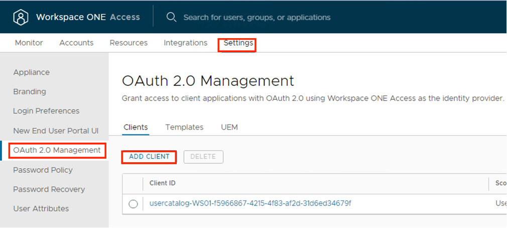
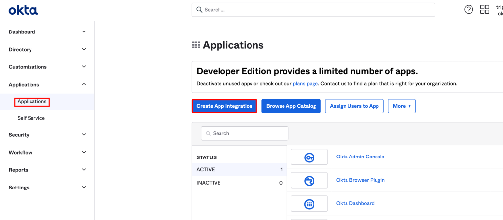
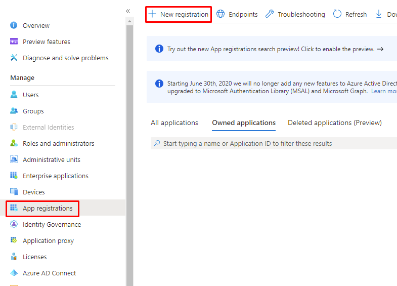
- In the Workspace ONE Access console Settings > OAuth 2.0 Management page, click ADD CLIENT.
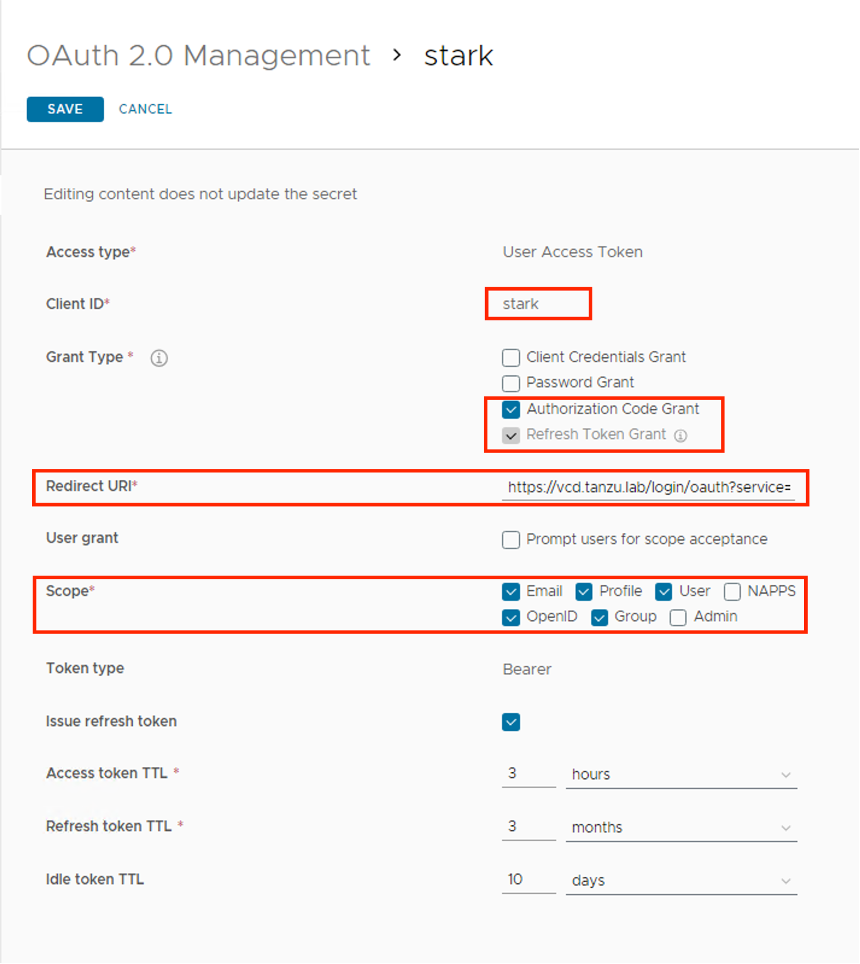
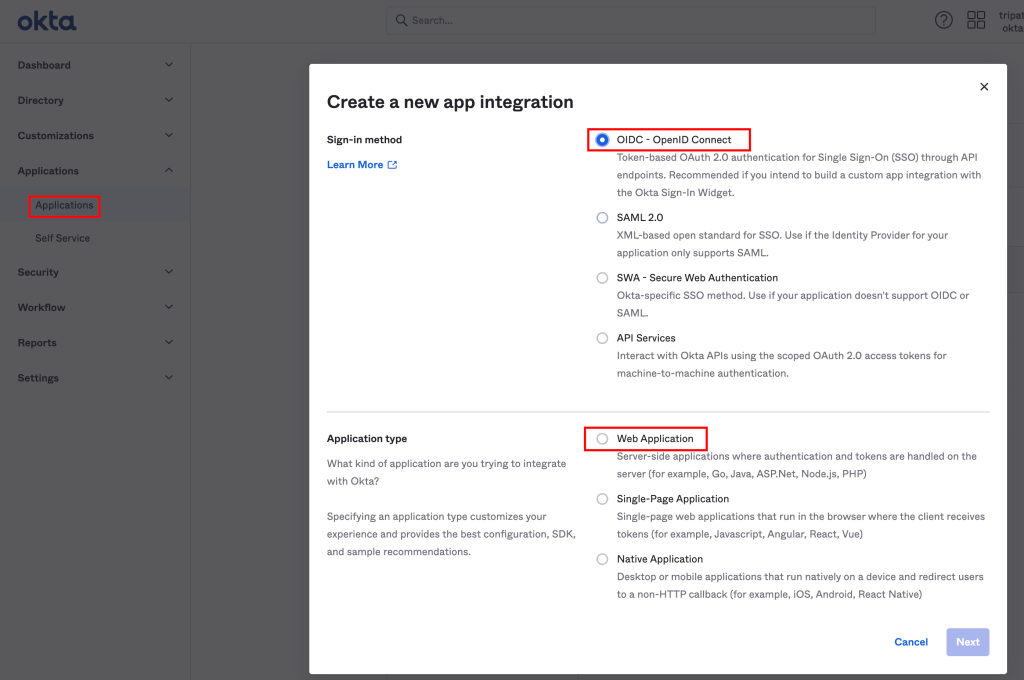
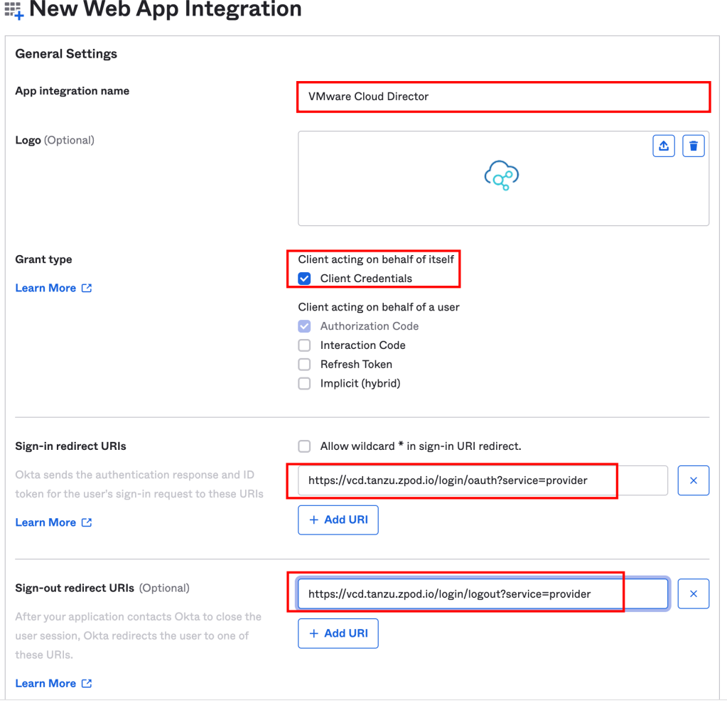
- In the Add Client page, configure the following.
| Label | Description |
| Access Type | Set to User Access Token |
| Client ID | Enter a unique client identifier for the Cloud Director Organization (System/Tenant) |
| Grant Type | Authorization Code Grant – When you select Authorization Code Grant, the Redirect URI setting is displayed under Grant Type. Refresh Token Grant – is enabled by default when the Issue refresh token setting is enabled. If you deactivate Issue refresh token, the Refresh Token Grant type is not checked. |
| Redirect URI | Retrieve this from VCD Provider/Tenant portal at: https://%5BVCD Endpoint]/(provider or tenant/[orgname])/administration/identity-providers/oidcSettings |
| Scope | The scope defines which part of the user’s account the token can access. The scopes you can select from include Email, Profile, User, NAPPS, OpenID, Group, and Admin. |
| Issue refresh token | To allow for the return of a refresh token, leave this option enabled. |
| Refresh token TTL | Set the Refresh Token time to live value. New access tokens can be requested until the refresh token expires. |
| Access token TTL | The access token expires in the number of seconds set in Access Token TTL. If Issue Refresh Token is enabled, when the access token expires, the application uses the refresh token to request a new access token. |
| Idle Token TTL | Configure how long a refresh token can be idle before it cannot be used again. |
| Token Type | For Workspace ONE Access, the token type is Bearer Token. |
| User Grant | Prompt users for scope acceptance is disabled. If Enabled users are shown message that lists the scopes that are being sent. |
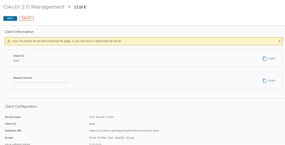
- Click SAVE. The client page is refreshed and the Client ID and the hidden Shared Secret are displayed.
- Copy and save the client ID and generated shared secret.
- Note: If the shared secret is not saved or you lose the secret code, you must generate a new secret, and update in Cloud Director that uses the same shared secret with the regenerated secret. To regenerate a secret, click the client ID that requires a new secret from the OAuth 2.0 Management page and click REGENERATE SECRET.
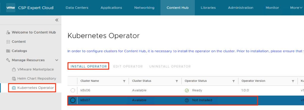
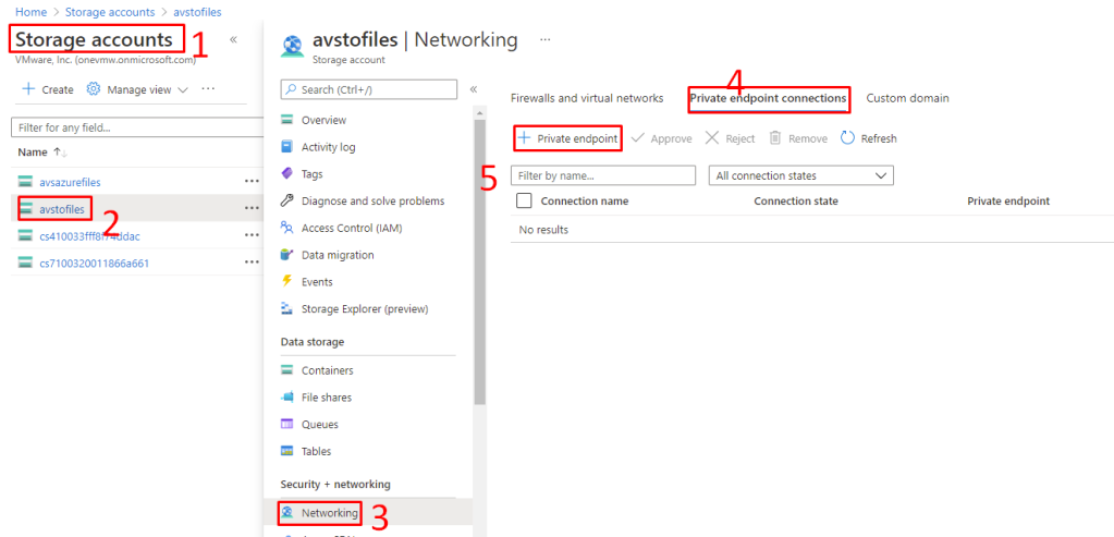
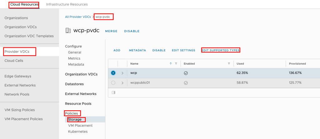
Steps to configure VMware Cloud Director to use Workspace ONE Access for Provider/Tenant users and groups
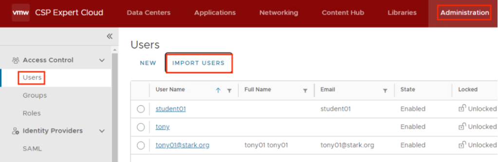
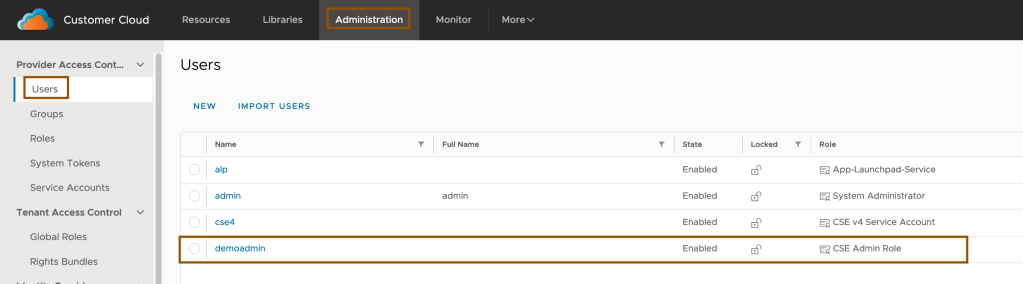
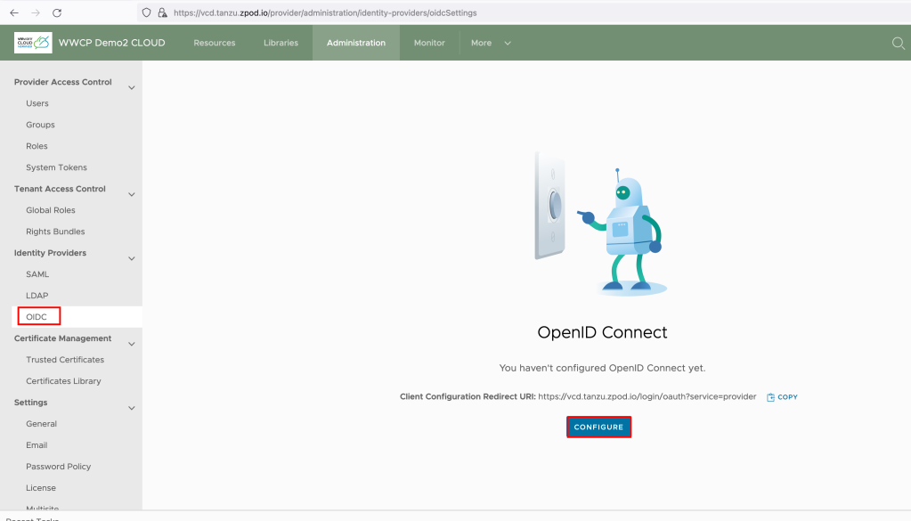
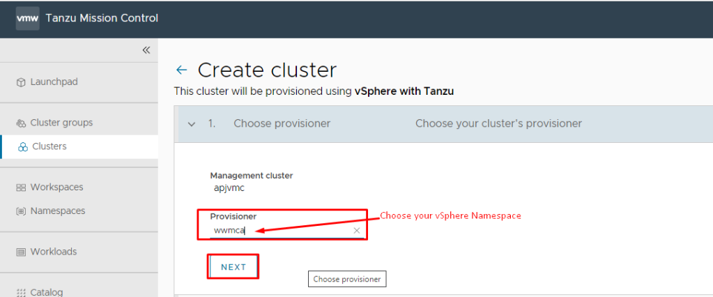
- From the top navigation bar, select Administration.
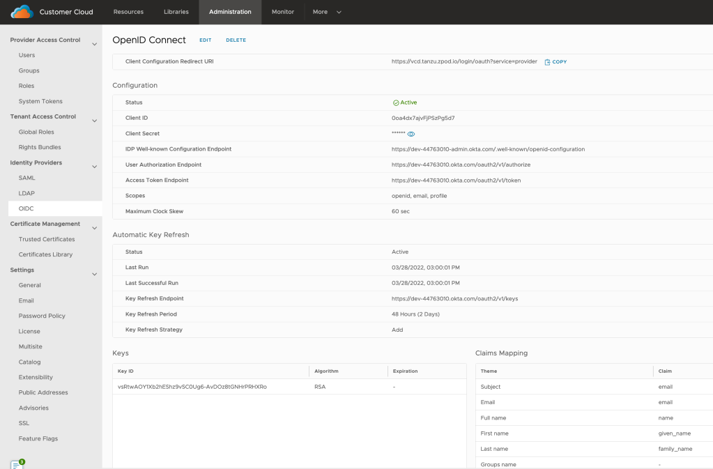
- In the left panel, under Identity Providers, click OIDC or directly you can browse: https:// [VCD Endpoint]/(provider or tenant/[orgname])/administration/identity-providers/oidcSettings
- If you are configuring OIDC for the first time, copy the client configuration redirect URI and use it to create a client application registration with an identity provider that complies with the OpenID Connect standard, for example, VMware Workspace ONE Access. (this has already been done above)
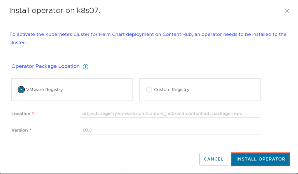
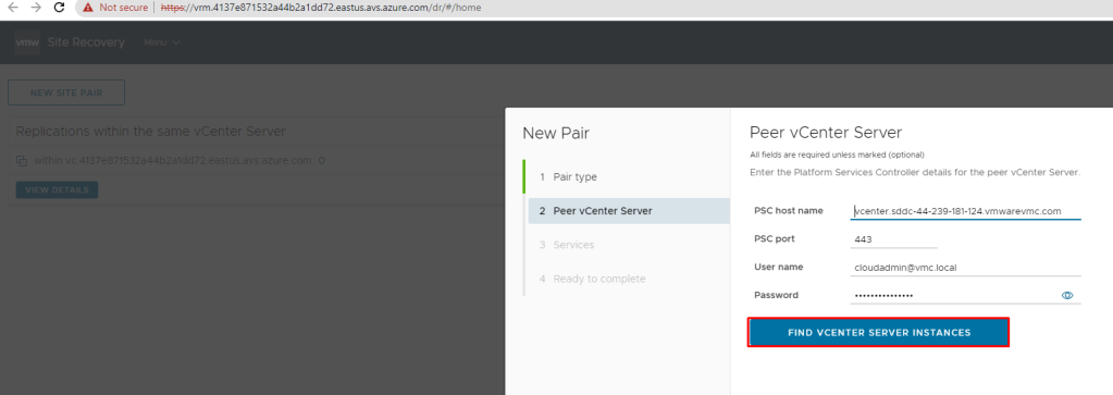
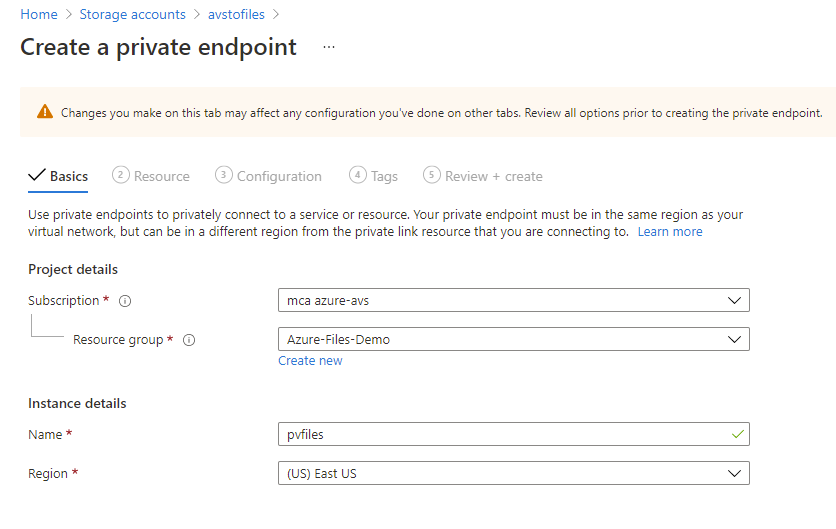
- Click Configure
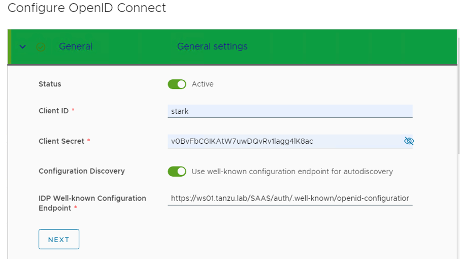
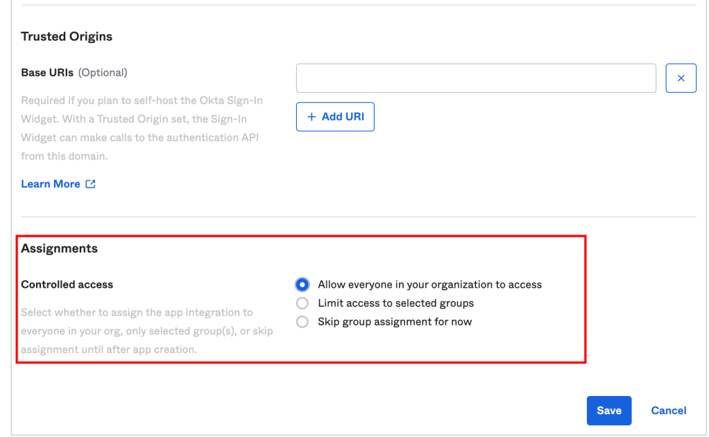
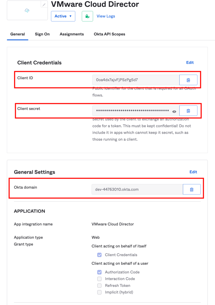
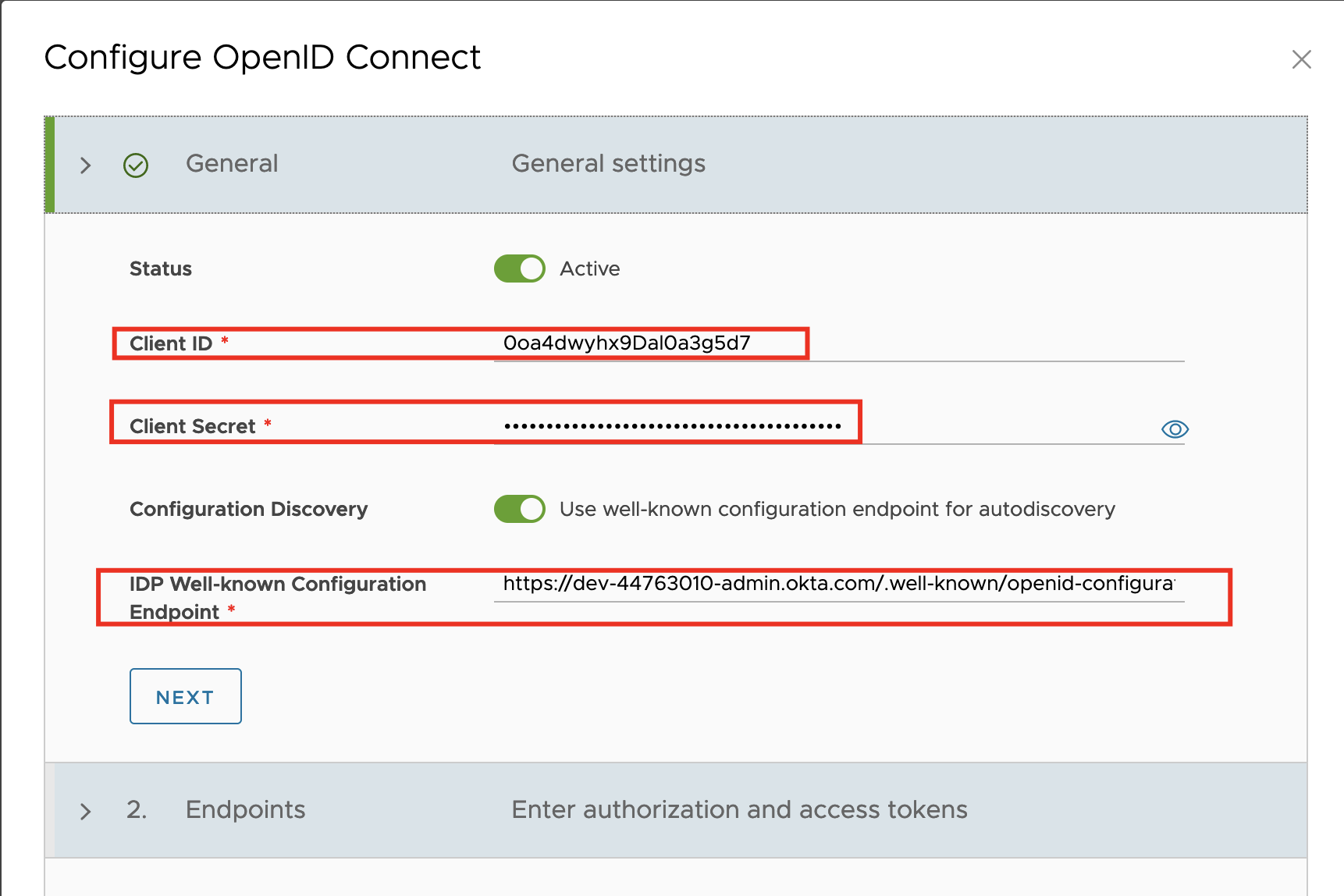
- Verify that OpenID Connect is active and fill in the Client ID and Client Secret you created in VMware Workspace ONE Access as above during client creation.
- To use the information from a well-known endpoint to automatically fill in the configuration information, turn on the Configuration Discovery toggle and enter a URL at the site of the provider that VMware Cloud Director can use to send authentication requests to. Fill in the IDP Well-known Configuration Endpoint field with the value: https://ws01 URL/SAAS/auth/.well-known/openid-configuration
- Click next.
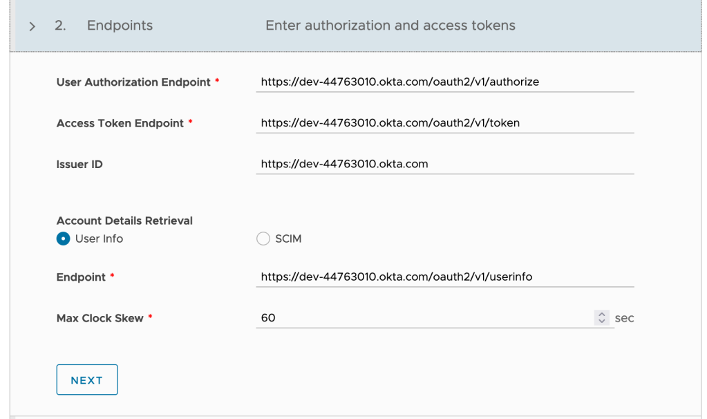
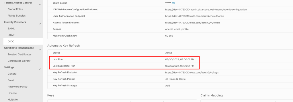
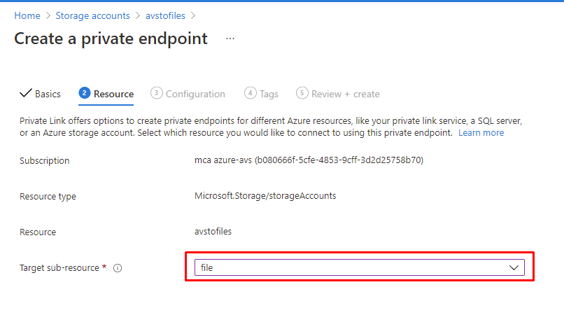
- If everything is correctly configured, the below information will automatically get populated, keep a note we are using the User Info endpoint.
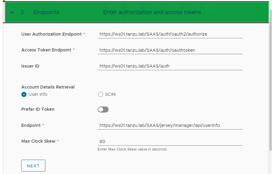
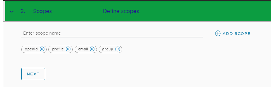
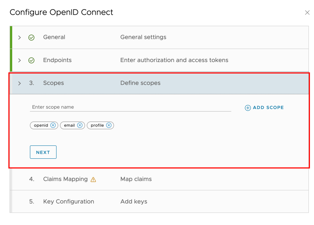
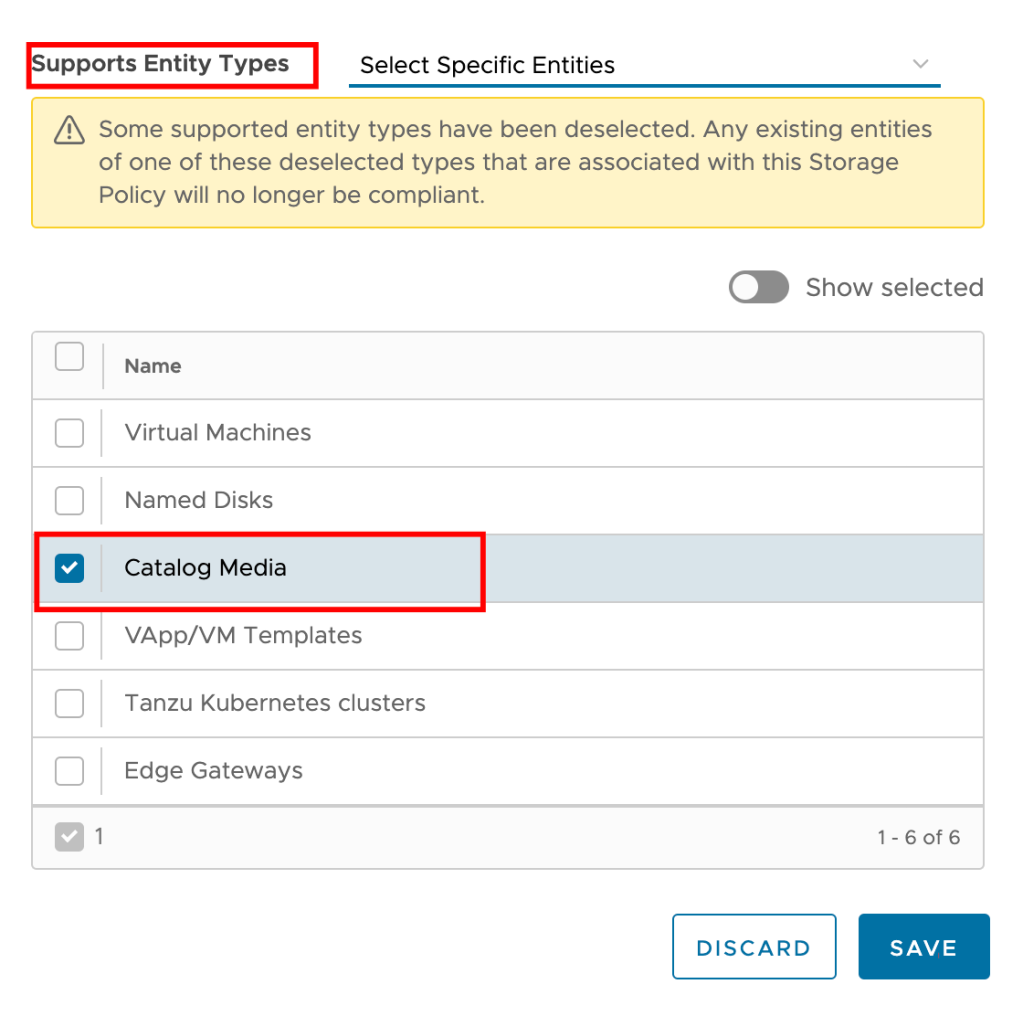
- VMware Cloud Director uses the scopes to authorize access to user details. When a client requests an access token, the scopes define the permissions that this token has to access user information, enter the scope information, and click Next.
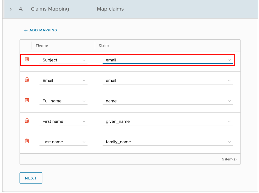
- Since we are using User Info as an access type, map the claims as below and click Next.
NOTE: At the claims mapping step, the Subject theme will be default populated with “sub” which will mean that VCD users will have the username format “[username]@XXX”. If you want to import the users to VCD with a different format, you can change the Subject theme to map to “email” and then import users to VCD using the email address attached to the account.
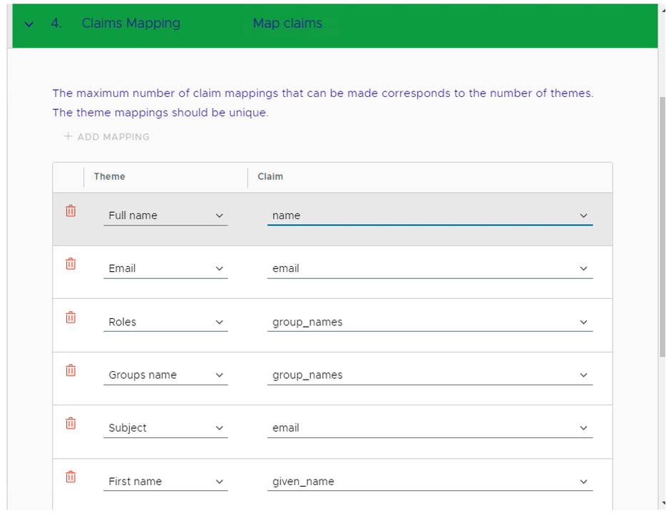
This is the most critical piece of configuration. Mapping this information is essential for VCD to interpret the token/user information correctly during the login process.
Login as an OIDC GROUP Member User
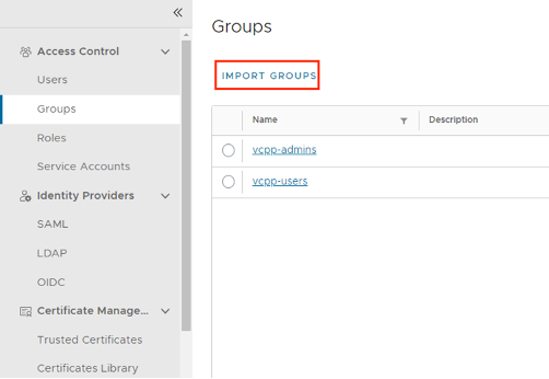
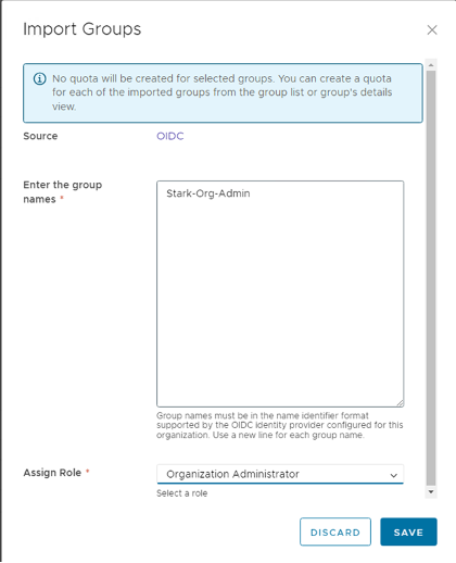
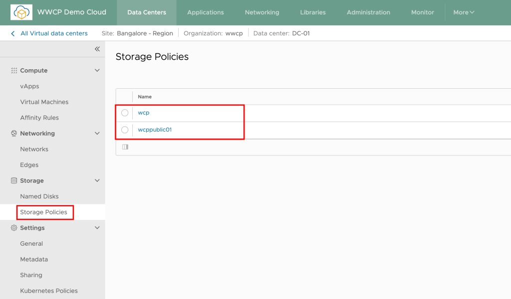
- In the Provider/Tenant organization’s Administration Page, import OIDC groups and map them to existing VCD roles.
- NOTE: In case you don’t see the “IMPORT GROUPS” button, refresh the page, and you will see the desired button IMPORT GROUPS
- User go to https:// [VCD Endpoint]/(provider or tenant/[orgname])
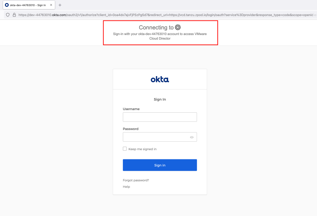
- The user should be redirected to the Workspace ONE Access login page. Users can log in with the user in the group.
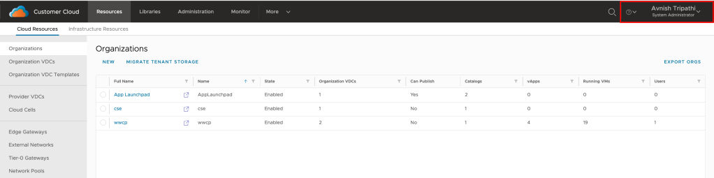
- The user will be redirected back to VCD and should now be fully logged in.
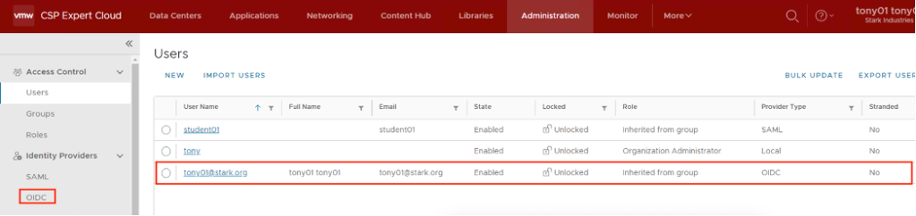
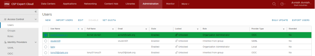
After the first successful login, the organization administrator can see the newly auto-imported user.
Login as an OIDC User
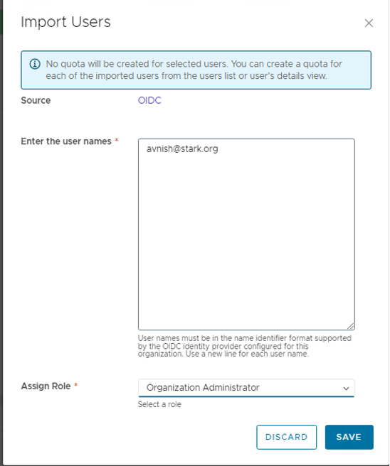
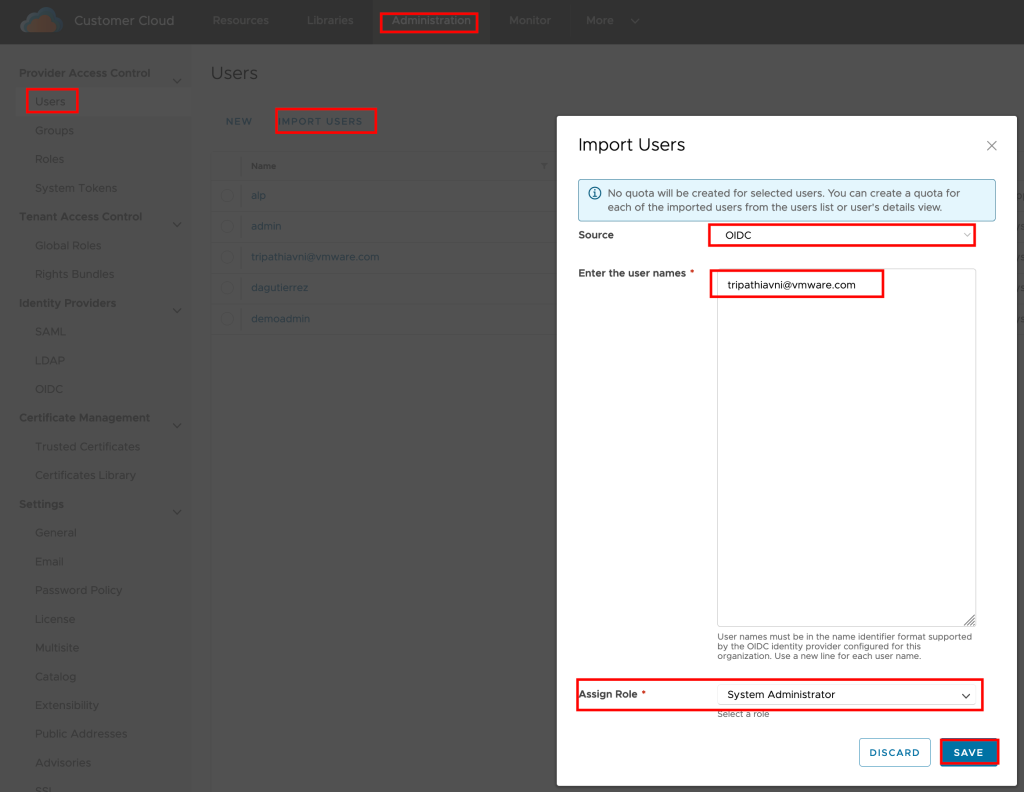
- In the Provider/Tenant organization’s Administration Page, import OIDC users and map them to existing VCD roles.
- User go to https://%5BVCD Endpoint%5D/(provider or tenant/[orgname])
- The user should be redirected to the Workspace ONE Access login page and log in there.
- The user will be redirected back to VCD and should now be fully logged in.
If you get the SSO Failure page double-check that you imported to the correct group/user and that the username format is correct. For additional information, you can check Here and for troubleshooting and about configuring additional logging, you can check the official documentation here.
Login without OIDC or as a Local User
In version 10.5, if an organization in VMware Cloud Director has SAML or OIDC configured, the UI displays only the Sign in with Single Sign-On option. To log in as a local user, navigate to https://vcloud.example.com/tenant/tenant_name/login or https://vcloud.example.com/provider/login.


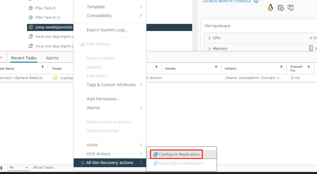


